|
Ningbo Paul Friction Material Co.,Ltd
|
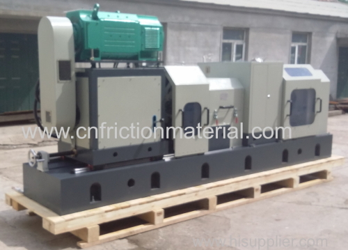
PFT 240 Clutch Facing Inertia Testing Machine
| Place of Origin: | Zhejiang, China (Mainland) |
|
|
|
| Add to My Favorites | |
| HiSupplier Escrow |
Product Detail
PFT 240 Clutch Facing Inertia Test Machine is designed and manufactured intl standard equipping clamp load testing machine.
PFT 240 Clutch Facing Inertia Testing Machine PFT 240 Clutch Facing Inertia Test Machine is designed and manufactured according to Raybestas RIP~Testprogram No.301,RIP~Testprogram No.3103,RIP~Test program No.3105 standards,equipping clamp load testing machine (including disc assembly thickness measurement).
I.Technical data 1. Test range:Dia200, Dia240, cover assembly and disc assembly; 2. Max. torque sensor:480Nm; 3.Max. test speed:3200r/min; 4.Motor power:76KW; 5.Clamp load:6000N; 6.Temperature measurement range: room temperature~400 degree centigrade +/-1%F.S 7.Temperature collection point: pressure plate and flywheel 8.Rotating inertia: 0.58 kg m2,2.0 kg m2,3.0 kg m2,3.11 kg m2 9.Engagement frequency:4 frequency/min 10.Separately equipped a cover assembly clamp load testing table for clamp load test of 200 and 240 cover assemlies
II Measurement accuracy 1.Torque sensor: +/-0.5% F.S; 2.Load sensor: +/-0.5% F.S; 3.Revolution sensor: +/-0.5% F.S; 4.Temperature sensor: +/-1.0% F.S;
III Structure The structure is horizontal type to simulate vehicle running condition, including main machine, pneumatic proportion control system, measurement and control system, speed controlling system. 1.Main machine consists of driving motor, speed measurement mechanism, inertia group, clutch installation mechanism, engagement mechanism, temperature measurement mechanism, torque measurement mechanism, safety protection mechanism, base and frame. 2.Measurement system: industrial computer, torque sensor amplifier, load sensor amplifier, temperature measurement device, speed measurement device, torque measurement, measurement modular, printer, measurement software and control software. All results show on the screen and can be printed out and saved. 3.Speed regulation and control system: speed regulation cabinet, Siemens converter, electrical control cabinet, PLC, general power switch, air switch, relay and buttons.
IV Features 1. The bearing base and support is fixing, movable support enlarge the supporting area. Adopt the good quality bearing. 2.Above the base, install the speed regulating motor, temperature measurement device, clutch (the relative release bearing can be installed), release mechanism, torque sensor, inertia flywheel group, brake motor (or special brake device), brake clutch. The support of inertia flywheel group locks driven part, and measure clutch static torque. 3. At the work position is set partial movable protective cover with observe window. 4. Adopt elastic coupling to keep the transmission with stability. 5. Assemble the torque sensor between inertia flywheel and tested clutch part. 6.Electrical part adopts PLC to control movements in order, industrial control computer collects and displays torque, temperature and rotate speed data, and draw the curve, calculate the result, save the data. Adopt PLC control movement in order and industrial control computer test all data. 7. Adopt Siemens converter with features of high reliability and fault alarm system. 8. Operation type: I.Auto test II.Manual test. 9. Cycle monitor: The machine has the function of monitor in the real time to make sure the reliability of test in cycles. Set the monitor at the position of release cylinder of engagement and disengagement and release position. 10. The computer output the signal to PLC, and PLC control relative parts' movement. The data of cycle frequency and test times is set by computer. 11. The machine has automatic audible and visual alarms and stops with the following conditions: a. over temperature cycle b. overspeed c. reaching test times d. general fault
V Test methods 1.Normal test * revolution n=1450rpm * Inertia I=3.0kg.m2 * Clutch:Dia200mm * Test process a. Disc assembly weighing and thickness measurement, cover assembly weighing and plot load characteristic curve. b. continuous 3000 cycles according to frequency of f=1.5min-1 c. Repeat "a" * Measurement torque and calculate friction value. 2. Middle energy test * revolution n=1470rpm * Inertia I=3.11kg m2 * Clutch:Dai200mm two sets * Test process a. Disc assembly weighing and measurement thickness, cover assembly weighing and measure disc assembly thickness at 4000 N, plot load characteristic curve. b. Engage and accelerate clutch inertia flywheel from 0rpm to 1470rpm, disengage it, brake clutch engagement to make inertia flywheel from 1470rpm to 0 rpm, according to frequency of f=1.2min-1 to finish 2500 cycles, cool down to room temperature, measurement functional wear of accelerating clutch and brake clutch. c. Engage and accelerate clutch to make inertia flywheel from 0rpm to 1470rpm and disengage it. Brake clutch engagement to make inertia flywheel from 1470rpm to 0 rpm. According to frequency of f=1.2min-1 finish 6000 cycles. cool down to room temperature, measurement functional wear of accelerating clutch and brake clutch. d. Engage and accelerate clutch to make inertia flywheel from 0rpm to 1470rpm and disengage it. Brake clutch engagement to make inertia flywheel from 1470rpm to 0 rpm. According to frequency of f=1.7min-1 finish 1500 cycles. cool down to room temperature, measurement functional wear of accelerating clutch and brake clutch. e. Disc assembly weighing and measurement thickness, cover assembly weighing and measure disc assembly thickness at 4000 N, plot load characteristic curve. * Test result: friction coefficient curve, wear rate, functional wear. 3. High energy test * revolution n=2125rpm * Inertia I=2.0kg.m2 * Engagement frequency:1 cycle/40 S, adjustable * Clutch:Dia200mm * Test process a. Disc assembly weighing and measurement thickness, cover assembly weighing and measure disc assembly thickness at 4000 N, plot load characteristic curve. b. Engagement 1000 cycles, measure functional wear at room temperature. c. Engagement 2000 cycles, measure functional wear at room temperature. d. Engagement 8000 cycles, measure functional wear at each 2000 cycle at room temperature. * Test result Average torque, average friction coefficient, wear rate and functional wear.
VI Working conditions 1 Power supply: power (3-phase and 5-wires) AC 380 V +/-10 %,single phase 220 V +/- 10 % 2 Operating temperature:5~40 degree centigrade; 3 Relative humidity:20~80% RH 4 Power frequency:50 Hz±2 % VII Main parts list
| ||||||||||||||||||||||||||||||||||||||||||||||||||||||||||||||||||||||||||||||||||||||||||||||||||||||||||||||||||||||||||||||||||||||||||||||||||||||||||||||||||||||||||||


